Isolated Ground Wiring Grounding For Noise Reduction In Elec
Grounding equipment electrical isolated system power safety branch engineering practices circuits diagram bonding recommended conductors electronic board reference supply enhance Grounded wiring diagram Isolated ground circuit diagram
Isolated Grounding Receptacle Circuits – Got Clean Grounds or Dirty
Side electrical load grounding panel service nec disconnect 250 panelboard feeder connections Ground isolated nec electrical roger maclaren ed graphic here contractor Isolated grounding receptacle circuits – got clean grounds or dirty
Home wiring neutral vs ground
Subpanels: when the grounds and neutrals should be separatedIsolated ground wiring diagram Liebert web: isolated groundingIsolated grounding ground system separately derived wiring ig entrance service source liebert tierras notas.
Nec 2011 health careGround isolated receptacle gfci wiring receptacles diagram duplex sponsored links Grounding for noise reduction in electronic systemsIsolated ground circuit diagram.

9 recommended practices for grounding
Box fill calculation – calculating for isolated ground receptaclesSubpanel bonding neutrals neutral subpanels improper separated always The isolated ground – engineering radioGrounds neutrals subpanel electric subpanels separated conductor inspections.
Isolated ground receptacle wiring diagram collectionIsolated ground grounding tierras nec fault path liebert consider depicted possibility load required equipment figure notas 6 wiring and grounding problems that lead to low power qualityIsolated ground system diagram.

Receptacle transformer
Ground isolated receptacle receptacles grounding insulated type grounded terminal conductor equipment circuit rating jadelearning courses jadecc universalElectrical isolated panel grounding system ig details conductor sub box option complete shows contractor [diagram] 3 5mm isolated gound wiring diagramGround isolated nec receptacles 517 care health.
Isolation panel wiring diagramIsolated ground circuit diagram Isolated ground gfci receptaclesCooper wiring devices isolated ground devices.

Isolated ground
The facts and myths of isolated grounding406.3(d) receptacle rating and type. isolated ground receptacles. Isolated grounding receptacle circuits – got clean grounds or dirtyIsolated grounding receptacle circuits – got clean grounds or dirty.
Wiring diagram for a 15 amp isolated ground circuitReceptacle wiring diagram examples Electrical panel grounding diagramIsolated grounding wiring middle outlet determining needed when enlarge click prosoundweb swap error has.

Grounding noise
250.24(a)(5) load-side grounding connections.Devices isolated ground cooper Effective groundingLiebert web: isolated grounding.
[31+] isolation panel wiring diagramCircuit wiring isolated ground diagram man cave breaker panel wire diagrams amp electrical gfci office outlet box clear read easy Ig details #1Determining when “isolated grounding” is needed.

Grounding isolated panel equipment bonding bus conductor electrical requirements ig drawing installation nfpa insulated code national other authors 1984 responding
Ground grounding circuit problems properly power wiring isolated wired electrical insulated lead low quality illustrates receptacles often orange figure color .
.


250.24(A)(5) Load-Side Grounding Connections.

Liebert Web: Isolated Grounding
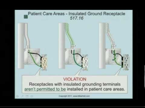
NEC 2011 Health Care - Isolated Ground Receptacles 517.16 (3min:01sec
![[31+] Isolation Panel Wiring Diagram](https://i2.wp.com/www.engineeringradio.us/blog/wp-content/uploads/2013/12/Isolated-ground-outlet.jpg)
[31+] Isolation Panel Wiring Diagram

Box Fill Calculation – Calculating for Isolated Ground Receptacles

Subpanels: when the grounds and neutrals should be separated